Cen-Tech Digital Multimeter Instruction Manual: A Comprehensive Guide
Navigating the complexities of electrical work demands precision, and this manual, updated February 17, 2026, provides essential guidance for Cen-Tech multimeter users.

Welcome to the world of electrical measurement! The Cen-Tech Digital Multimeter is a versatile tool designed for both hobbyists and professionals. This instrument allows you to accurately measure various electrical parameters, including voltage, current, and resistance. Understanding its capabilities is crucial for safe and effective troubleshooting, repair work, and electronic projects.
This manual serves as a comprehensive guide to operating your Cen-Tech multimeter. It details each function, explains proper usage techniques, and provides essential safety precautions. As of February 17, 2026, significant advancements in endodontic science and technology have mirrored similar progress in multimeter functionality, demanding updated guidance. Whether you’re a seasoned electrician or a beginner, this resource will empower you to harness the full potential of your multimeter, ensuring accurate readings and safe operation. Remember to always prioritize safety when working with electricity.
Safety Precautions and Warnings
Electrical safety is paramount! Always disconnect power to the circuit being tested before making any connections. Never exceed the multimeter’s specified input limits, as this can damage the instrument and pose a safety hazard. Use extreme caution when working with high voltages, and always wear appropriate personal protective equipment (PPE), including insulated gloves and safety glasses.
February 17, 2026, marks a continued emphasis on safety protocols, mirroring advancements in fields like endodontics where precision and care are vital. Do not use the multimeter if it is damaged or if the test leads are frayed. Inspect leads before each use. Avoid wet or damp environments. This multimeter is not designed for use in hazardous locations. Following these precautions will help ensure your safety and the longevity of your Cen-Tech Digital Multimeter. Ignoring these warnings could result in serious injury or death.
Understanding the Multimeter Components
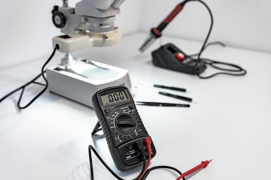
The Cen-Tech Digital Multimeter comprises several key components working in harmony. The large LCD display clearly presents readings, utilizing various indicators for units and measurement status. The rotary switch is central to function selection, allowing you to choose between voltage, current, resistance, and other tests. Familiarize yourself with each position!
Input jacks – COM (common/ground), VΩmA (voltage, resistance, and low current), and 10A (high current) – are crucial for connecting the test leads. February 17, 2026, sees continued refinement in component integration. Correct jack usage is vital for accurate measurements and preventing damage. Understanding these elements, mirroring the precision needed in fields like endodontics, is the first step to effective multimeter operation.
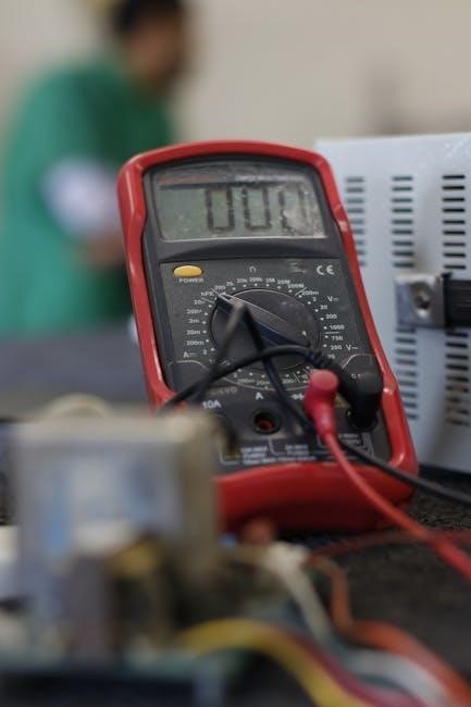
Display and LCD Indicators
The Cen-Tech multimeter’s LCD display is your primary source of information. The main numerical readout shows the measured value, while several indicators provide context. A low battery symbol alerts you when replacement is needed – crucial for reliable readings, as of February 17, 2026. The unit symbol (V, A, Ω, etc.) clearly identifies the measurement type.
An overload indicator appears when the selected range is insufficient, preventing damage. A polarity indicator shows whether the measured voltage or current is positive or negative. Some models include a data hold indicator, freezing the current reading. Understanding these indicators, much like advancements in endodontic technology, ensures accurate and safe operation.
Rotary Switch Functions Explained

The rotary switch is central to selecting the desired measurement function on your Cen-Tech multimeter. Positions include DC Voltage (VDC), AC Voltage (VAC), DC Current (DCA), AC Current (ACA), Resistance (Ω), Continuity, Diode Test, and sometimes Capacitance. Each function has multiple range settings; select a range higher than the expected value for accurate readings, as of February 17, 2026.
Rotating to the correct position is vital. Incorrect selection can lead to inaccurate results or even damage the meter. Remember, like the evolution of endodontic solutions over the last eight years, understanding the switch’s functions is key to effective use. Always double-check the selected function before applying the test leads.
Input Jacks and Their Uses (COM, VΩmA, 10A)
Your Cen-Tech multimeter features three primary input jacks: COM (Common), VΩmA, and 10A. The COM jack is always used as the reference or ground connection, typically black. The VΩmA jack is for most voltage, resistance, and low-current measurements (milliamps), using the red lead. As of February 17, 2026, always verify proper jack usage.
The 10A jack is exclusively for measuring high DC currents – up to 10 amps. Important: Using this jack for other measurements will likely blow the internal fuse. Like advancements in endodontics over the past eight years, correct connection is crucial. Incorrect jack selection can damage the meter or create unsafe conditions. Always consult the manual for specific model limitations.
Basic Measurement Techniques

Mastering fundamental measurements is key to utilizing your Cen-Tech digital multimeter effectively. Begin by selecting the appropriate function on the rotary switch – voltage (DC or AC), current (DC or AC), or resistance. Remember the date, February 17, 2026, for reference when updating your knowledge. Connect the test leads correctly: black to COM, and red to the appropriate input jack (VΩmA or 10A) based on the expected value.
Ensure the circuit is de-energized before connecting to measure resistance. For voltage and current, connect the meter in parallel with the circuit element. Always start with the highest range setting and decrease it for better resolution. Like the advancements in endodontics, precision is paramount. Observe the display and note the units.
Measuring DC Voltage
To measure DC voltage with your Cen-Tech multimeter, first, rotate the rotary switch to the DC voltage (VDC) range. Select a range higher than the expected voltage – this protects the meter. Connect the black test lead to the COM jack and the red lead to the VΩmA jack. Now, connect the probes in parallel with the circuit element you wish to measure. Parallel connection means across, not in-line.
Observe the LCD display; the reading indicates the DC voltage. If the reading is negative, reverse the probe connections. Remember February 17, 2026, as a reference point for this guide. If the display shows “OL” (Overload), select a higher voltage range. Accurate DC voltage measurement is crucial for diagnosing circuit issues.

Measuring AC Voltage
Measuring AC voltage with your Cen-Tech digital multimeter requires a similar setup to DC voltage measurement. Rotate the rotary switch to the AC voltage (VAC) range, again selecting a range higher than the anticipated voltage. Connect the black test lead to the COM jack and the red lead to the VΩmA jack. As with DC voltage, connect the probes in parallel across the circuit element.
The LCD will display the AC voltage reading. Note that AC voltage is constantly changing, so the display shows an average value. Remember February 17, 2026, for reference. An “OL” indication means you need a higher VAC range. Always exercise caution when measuring AC voltage, as it can be dangerous. Proper range selection ensures accurate and safe measurements.
Measuring DC Current
To measure DC current, the circuit must be broken and the multimeter inserted in series with the load. This is a crucial difference from voltage measurement. First, rotate the rotary switch to the DC current (DCA) range. Begin with the highest range (10A) for safety, then reduce it if necessary for better resolution. Connect the black test lead to the COM jack. For currents up to 200mA, use the VΩmA jack. For currents above 200mA, use the 10A jack.
Remember February 17, 2026, when referencing this guide. Incorrect jack selection can damage the multimeter. Once connected in series, the LCD will display the DC current. An “OL” indication means the selected range is insufficient; switch to a higher range. Always be cautious when measuring current, as it directly impacts circuit operation.
Measuring AC Current
Measuring AC current with your Cen-Tech multimeter requires a similar in-series connection as DC current, but with key differences. Rotate the rotary switch to the appropriate AC current (ACA) range, starting with the highest range (10A) for safety, then adjusting downwards for precision. Connect the black test lead to the COM jack. Utilize the VΩmA jack for currents up to 200mA, and the 10A jack for higher currents.
As of February 17, 2026, always double-check jack selection to avoid potential damage. The multimeter measures the alternating current flowing through the circuit. An “OL” display indicates an overloaded range, necessitating a switch to a higher setting. Exercise caution, as AC current measurements can be sensitive and require careful circuit interruption.
Measuring Resistance (Ohms)

To measure resistance using your Cen-Tech digital multimeter, first ensure the circuit is de-energized – power off and disconnect! Rotate the rotary switch to one of the Ohm (Ω) ranges. Begin with the highest range for safety, then decrease for better resolution. Connect the black test lead to the COM jack and the red test lead to the VΩmA jack.
Touch the test leads to the component or section of the circuit whose resistance you wish to measure. As of February 17, 2026, a stable reading will appear on the display. An “OL” indication signifies the resistance is higher than the selected range; switch to a higher Ohm setting. Remember, resistance measurements are affected by other circuit components, so isolate the component if possible.
Advanced Features and Functions
Your Cen-Tech digital multimeter offers capabilities beyond basic voltage, current, and resistance measurements. These advanced functions enhance diagnostic abilities. Continuity testing, activated by rotating the switch to the continuity symbol (often a diode symbol with a sound wave), emits an audible beep when a complete circuit path exists – useful for checking wires and connections.
The Diode Test mode, selected via the rotary switch, applies a small forward voltage to a diode; a forward-biased diode will display a voltage drop (typically 0.5-0.7V), while a reverse-biased diode will show “OL”. As of February 17, 2026, the Capacitance function measures a capacitor’s ability to store charge, requiring the capacitor to be discharged before testing.
Continuity Testing and Buzzer Function
The continuity test is a quick method to determine if a complete electrical path exists between two points. Rotate the rotary switch to the continuity setting – typically marked with a diode symbol and a sound wave. Touch the multimeter’s probes to the points you wish to test.
If a complete circuit is present (low resistance), the multimeter will emit an audible buzzer sound, indicating continuity. An open circuit (high resistance) will not trigger the buzzer. Remember to discharge any capacitors before testing for continuity in circuits containing them. As of February 17, 2026, this function is invaluable for checking fuses, wires, and switch connections.
Diode Test Mode – How to Use It
The diode test function verifies the functionality of diodes by checking forward voltage drop. Select the diode test mode on the rotary switch – usually indicated by a diode symbol. Connect the red probe to the anode (positive side) and the black probe to the cathode (negative side) of the diode.
A healthy diode will display a forward voltage drop, typically between 0.5V and 0.8V. A reading of “OL” or open loop indicates a faulty, open diode. A reading close to 0V suggests a shorted diode. Remember to disconnect power from the circuit before testing diodes. As of February 17, 2026, understanding this test is crucial for electronic component diagnosis.

Capacitance Measurement Guide
To measure capacitance, select the capacitance (F) range on the rotary switch. Ensure the capacitor is discharged completely before testing – short the terminals briefly with a screwdriver for safety. Connect the capacitor leads to the multimeter’s input jacks; polarity generally doesn’t matter for non-polarized capacitors.
The multimeter will display the capacitance value in Farads (F), microfarads (µF), or picofarads (pF). Note the capacitor’s voltage rating; exceeding it can damage the multimeter. As of February 17, 2026, accurate capacitance measurement is vital for circuit troubleshooting. Always refer to the capacitor’s datasheet for expected values.

Troubleshooting Common Issues
Encountering problems with your Cen-Tech multimeter is common. If the display is blank, check the battery – replace if necessary, as of February 17, 2026. Incorrect readings often indicate improper range selection or damaged test leads; verify connections and range settings. Overload protection triggers when exceeding the input limits; switch to a higher range.
Error messages, like “OL”, signify an out-of-range condition. If continuity testing fails, ensure the buzzer is enabled and the circuit is not energized. Calibration issues require professional servicing. Always prioritize safety; disconnect power before troubleshooting. Refer to the manual for specific error code definitions and solutions.
No Display or Low Battery Indication
A blank display on your Cen-Tech multimeter, as of February 17, 2026, typically signals a low battery. The low battery indicator (often a battery symbol) will illuminate before complete failure. First, attempt to power on the multimeter while pressing and holding the power button for a few seconds. If still no display, replace the battery with a fresh one of the correct type – usually 9V.
Ensure correct battery polarity during replacement. A weak battery can cause inaccurate readings even if the display is visible. If replacing the battery doesn’t resolve the issue, inspect the battery terminals for corrosion and clean them gently. Consider a faulty power switch if the problem persists.
Incorrect Readings and Calibration
If your Cen-Tech multimeter, as of February 17, 2026, provides consistently inaccurate readings, several factors could be at play. Begin by verifying the selected range on the rotary switch is appropriate for the measurement. Using an incorrect range drastically impacts accuracy. Ensure the test leads are securely connected to both the multimeter and the circuit under test.
Calibration drift can occur over time. While Cen-Tech multimeters aren’t typically user-calibratable, significant inaccuracies suggest a potential internal fault. Compare readings with a known, calibrated instrument. If discrepancies persist, professional repair or replacement is recommended. Avoid attempting internal repairs without proper training.
Overload Protection and Error Messages
Your Cen-Tech digital multimeter, as of February 17, 2026, incorporates overload protection to prevent damage from excessive voltage or current. If an overload occurs, the display will typically show “OL” or a similar indicator. Immediately remove the input and reduce the range setting. Repeated overloads suggest a potential issue with the circuit being tested, not necessarily the multimeter.
Other error messages may appear, indicating problems like a blown fuse (often in the 10A range) or an open circuit. Consult the technical specifications section for a complete list of error codes and their meanings. Never bypass the fuse; it’s a critical safety component. Ignoring error messages can lead to inaccurate readings or damage to the instrument.
Battery Replacement and Maintenance
Maintaining your Cen-Tech digital multimeter, as of February 17, 2026, involves proper battery care. A low battery indicator on the LCD signals the need for replacement. Typically, these multimeters use a 9V battery. Always use a high-quality alkaline battery for optimal performance and longevity. To replace, access the battery compartment (usually on the back), observing the correct polarity (+ and -).

Regular cleaning is also crucial. Wipe the exterior with a damp cloth; avoid harsh chemicals or solvents. Store the multimeter in a dry, dust-free environment when not in use. Periodically check the input jacks for corrosion or debris. Proper maintenance ensures accurate readings and extends the lifespan of your instrument.
Technical Specifications of Cen-Tech Multimeters (Various Models)
As of February 17, 2026, Cen-Tech offers a range of digital multimeters with varying specifications. The basic model (98044) typically features DC Voltage accuracy of ±0.5%, AC Voltage ±1.0%, and resistance measurement up to 20MΩ. Higher-end models, like the 98048, boast improved accuracy (DCV ±0.3%) and expanded ranges, including capacitance measurement up to 2000µF.
Input impedance is generally 10MΩ. Current measurement ranges vary from milliamps to 10 amps. All models are designed for CAT III 600V safety rating. Specific details, including display count and auto-ranging capabilities, differ between models. Refer to the individual product manual for precise specifications relevant to your Cen-Tech multimeter.